
Enhancing LNG Pump Efficiency: GTT's Innovations in Sump and Bucket Solutions
The pumpable volume of liquefied natural gas (LNG) within cargo and fuel tanks plays a pivotal role in vessel design. For LNG carriers, it dictates the cargo quantity deliverable without compromising ballast voyages, while for LNG-fuelled vessels, it influences the navigational range achievable based on specific main engine consumption rates.
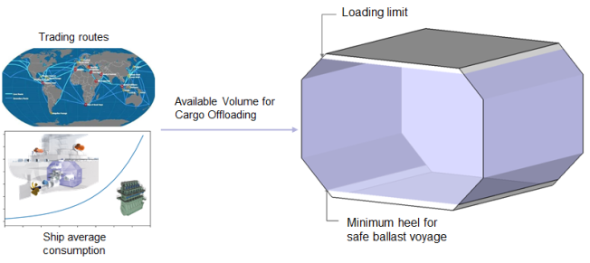
Recognizing this critical aspect, GTT has introduced enhancements to its sump solution. This upgraded system ensures the sustained operation of fuel pumps in LNG, irrespective of prevailing sea conditions, while simultaneously reducing the minimum heel required to operate the pump(s).
Optimized sump design
The process of adjusting the sump's height using shims was deemed time-consuming and labour-intensive. In response to these concerns, GTT has engineered a new design tailored to meet the specific needs of shipyard production departments.
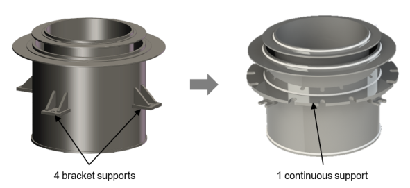
Figure 1 – old design versus new design
The up-graded design replaces the previous four supports with a continuous disc resting on four circular wooden beams. This modification not only distributes load more evenly but also ensures a more uniform heat distribution, contributing to improved operational efficiency. Height adjustment is now simplified, achieved with mastic, eliminating the need for on-board machining.
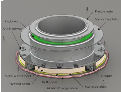
Figure 2 – New sump with mastic
This innovative design is projected to reduce installation time by at least 50%, with the first application anticipated in summer 2025. Furthermore, this solution is versatile, applicable to both MARK III and NO technologies, offering enhanced flexibility and reliability across different vessel configurations.
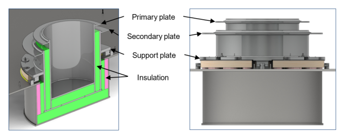
Figure 3 – At left, side view / at right, cross sectional view
Adaptation for NO96 Cargo Containment System (CCS)
In response to customer requests for a sump solution compatible with NO96 technology, GTT has recently conducted validation tests on the mechanical strength and fatigue of NO96 CCS with the integration of a sump. Given the technological characteristics of the NO96 CCS, the decision was made to position the sump strategically in front of the pump tower, as shown in figure 3.
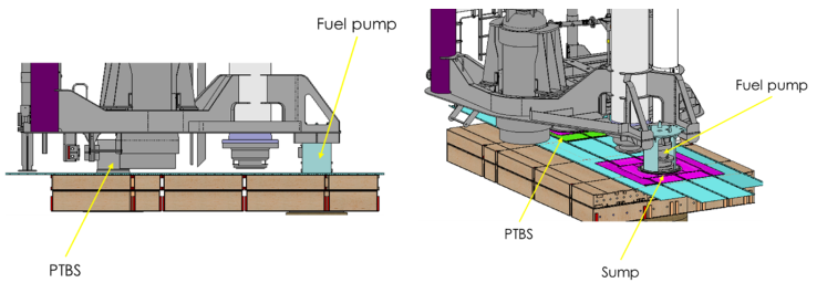
Figure 4 – Sump position with NO96 CCS
This positioning necessitates the application of a 20 mm seam weld locally around the sump, specifically at junctions measuring 1.5/1.0mm and 1.0/0.7mm. Additionally, the INVAR tongues need to be increased locally around the sump to ensure structural integrity and operational efficiency.
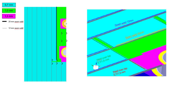
Figure 5 – Membrane arrangement (primary & secondary)
To address clearance considerations associated with the liquid dome, GTT has developed a design featuring a removable pump support, facilitating the installation of the tripod mast. The installation procedure involves fixing the first part (highlighted in green in below illustration) directly onto the emergency pipe in the workshop. Subsequently, upon insertion of the mast into the tank, the pump support and the pump are bolted securely into place.
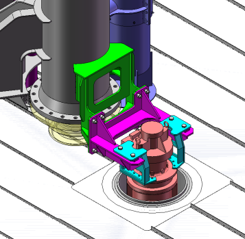
Figure 6 – Fuel pump on its removable support positioned in the sump
Furthermore, oblong holes integrated into the pump support, along with the use of shims between the pump and the support, enable adjustment in three directions, optimizing pump positioning and ensuring optimal performance in various operating conditions.
GTT has recently introduced a reduced combined dome specifically designed for LNG-fuelled ships equipped with Mark III tanks. This innovative development capitalizes on the unique spatial challenges associated with such vessels compared to traditional LNG carriers. By integrating a reduced dome and a corresponding pump tower, GTT offers enhanced flexibility in tank design, containment system installation, and cost-effectiveness.
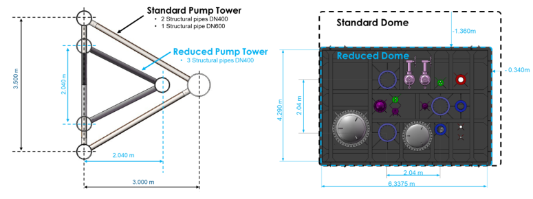
Figure 7 - Size reduction of rectangular combined dome and pump tower
The reduction in dome size, depicted in the above figure, optimizes space utilization without compromising operational efficiency, catering to the evolving requirements of LNG-fuelled vessels. In line with GTT's commitment to innovation and adaptability, the company is currently in the process of validating a new sump position for the reduced dome configuration.
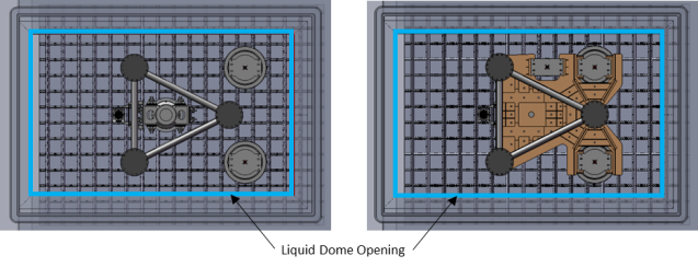
Figure 8 - Rectangular reduce combined dome and pump tower with 2 submerged fuel pumps in 2 sumps
This new sump position allows two submerged pumps to be directly fixed onto the mast without the requirement for removable parts. As illustrated in above picture, these pumps will be installed in two separate sumps, offering redundancy and minimizing operational constraints associated with submerged fuel pumps.
By offering dual sumps in the reduced combined dome configuration, GTT is addressing the requirements highlighted by customers regarding redundancy and fewer operational constraints in the use of submerged fuel pumps.
Revolutionizing Bucket Solutions
In scenarios where the traditional sump solution proves impractical, GTT offers an alternative: the bucket solution. This innovative approach aims to minimize the minimum heel required for pump operation whilst minimising the possibility of a pump tripping. The bucket solution involves the strategic placement of a retaining plate around the pump to retain LNG during periods of low liquid levels caused by ship movements.
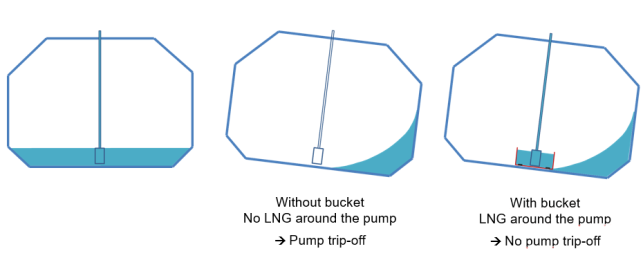
Figure 9 – Illustration of bucket principle
While conventional bucket solutions typically require top filling and a substantial heel to operate effectively, GTT has engineered a solution featuring a bottom filling capability.
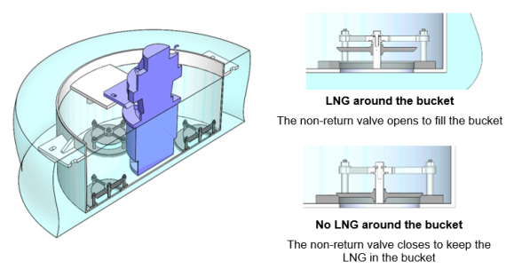
Figure 10 – Illustration of non-return valves in the bucket design
By incorporating non-return valves into the bucket design, GTT enables bottom filling, reducing the height of the heel required for pump operation. This design innovation ensures uninterrupted pump operation, even when the liquid level falls below the height of the bucket, mitigating the risk of pump tripping.
The non-return valves are constructed from lightweight aluminium with excellent mechanical properties, ensuring durability and reliability. Supported by stainless steel valve supports, these valves are strategically positioned at the bottom of the bucket, preferably located at the rear of the pump mast.
In conclusion, GTT's innovative bucket solution represents a significant advancement in LNG pump efficiency, offering practical alternatives for seamless operation in diverse operating conditions. By leveraging cutting-edge design principles and materials, GTT continues to redefine industry standards and empower LNG vessel operators with reliable and efficient solutions.